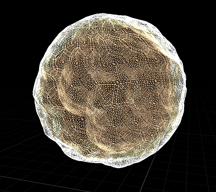
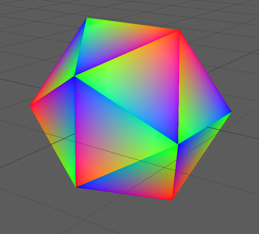
This week we thought we’d share some of the technical details of our implementation of Act 2 which is entirely computer generated imagery. The geometry of the cage is no more than an icosahedron. The smooth line and the face fading in effect are implemented based on barycentric coordinate. We split the shared vertices to ensure each face/triangle has its own three vertices. For each triangle we assign a unique barycentric coordinate as vertex to three vertices. After rasterization the coordinates are interpolated among pixels which can finally be used to determine distance to triangle boundary, and used to shade edges. The shattering effect of cage is based on UE4 destructible mesh which creates the debris pattern based on voronoi diagram. The shape of orb is even simpler: it’s just a sphere. However, we added a bunch of details to it based on displacement mapping and normal mapping. Textures are procedurally generated from noises. In order to prevent the uv distortion of sphere, a technique named tri-planar texturing was employed. TPT is a blending of three sets of textures based on the normal direction of each pixel. On top of that, we animated the surface of the orb by panning uv coordinates. Finally, the particles are driven by vector field created using Maya’s Fluid Simulator. A vortex and a turbulence component are added so that particles are moving in a more interesting way.
The cage:
The orb:
Normal map
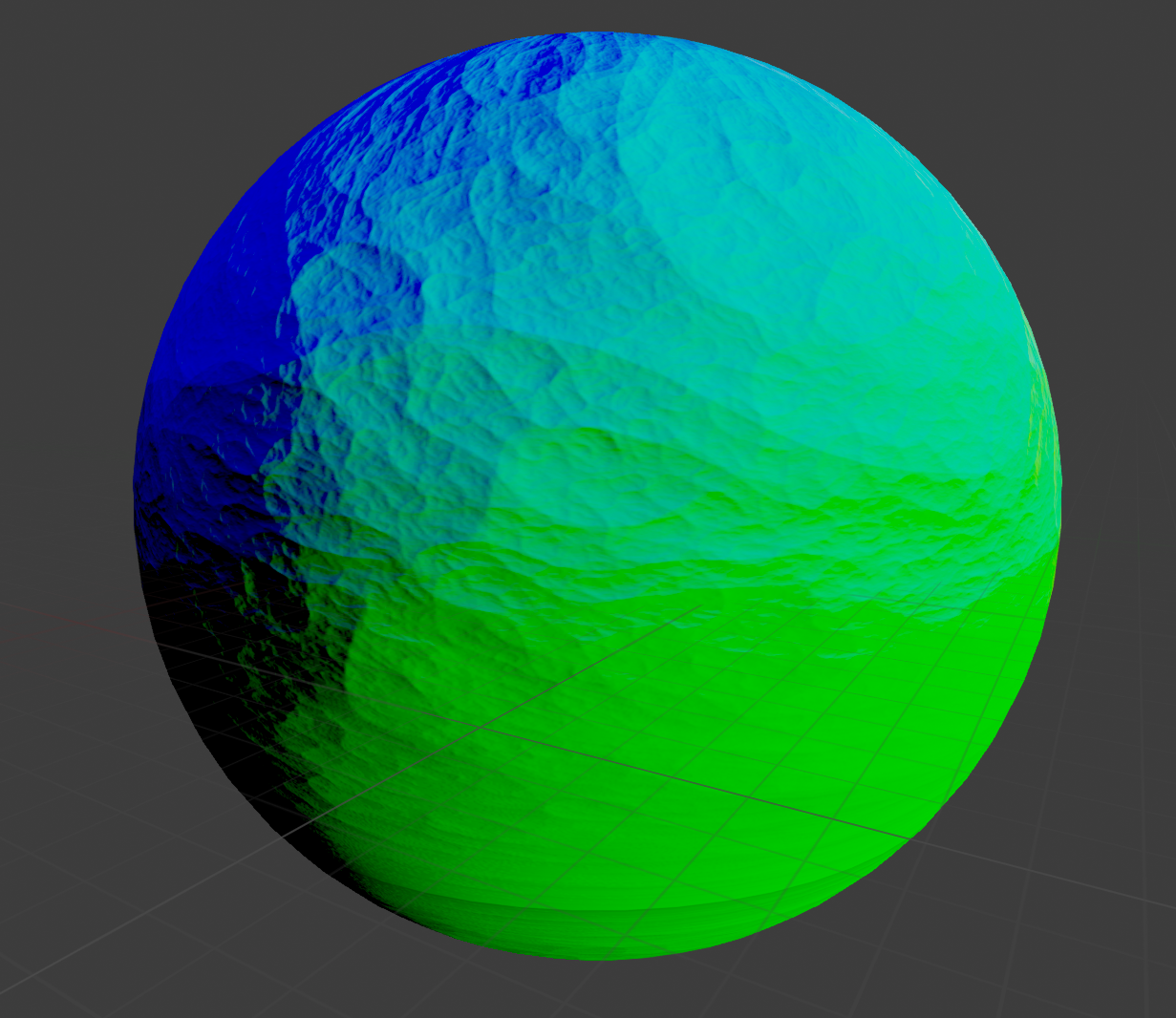
Computer generated texture