
Controlling a Large Number of LEDs with a Single Arduino
The first big technical challenge for our team was figuring out how we were going to use a single Arduino to drive the huge number of LEDs that we need for our project. Current limits aside, the main issue was how we would be able to send signals to about 72 different LED arrays with the Arduino Uno’s 14 outputs.
IDEA #1: A GAZILLION MULTIPLEXERS
My first idea was to use one output as a PWM data line and use seven other outputs as digital selectors for a 128:1 demultiplexer. I don’t know why this was my first thought. I guess I never actually wrote down the words “128:1 demultiplexer” because, if I had, I think I would have immediately vetoed the idea for being insane.

Crazy!
In this design, the data line coming out of the Arduino would have carried a PWM signal between 0 and 255. This PWM signal would have then been transformed into an analog voltage signal between 0 and 5V with the simple but reliable RC-filter shown below.
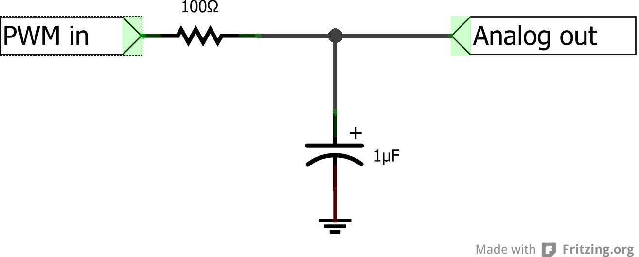
PWM-to-analog converter
Now that I had an analog voltage, all I needed to do was pass it to the LED array. Unfortunately, since I had 71 other LED arrays to send signals to, I had to figure out a way to latch this analog voltage either indefinitely or at least until I finished sending signals to the other 71 LED arrays. Looking up “analog voltage latch” in Google led me to the “sample-and-hold circuit,” which seemed sort of promising. The only problem was that sample-and-hold circuits can only hold analog voltage values for a really, really short amount of time before the value decays due to capacitor leakage. Bleak, but I figured there was a chance I could switch between the 72 LED arrays quickly enough to prevent the sampled voltage from decaying noticeably before the next sample was taken. I had the components needed to try it out, so why not, right? So I combined all the pieces of my puzzle — sans demuxes — and ran a simple Arduino program that sent out a PWM signal for 100 ms, paused for 100 ms, and then repeated. If my circuit worked perfectly, I wouldn’t see any change in intensity in the LED.
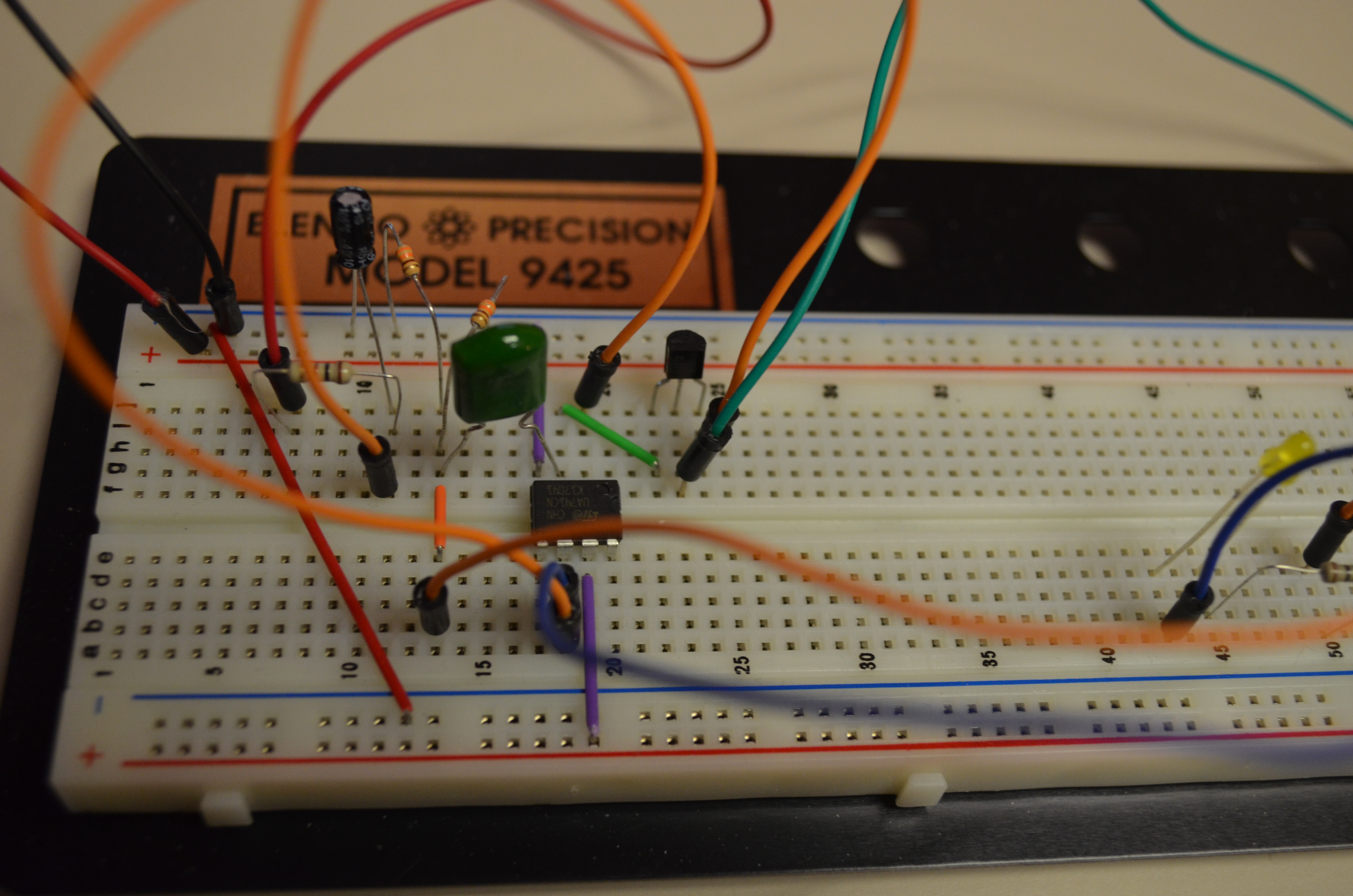
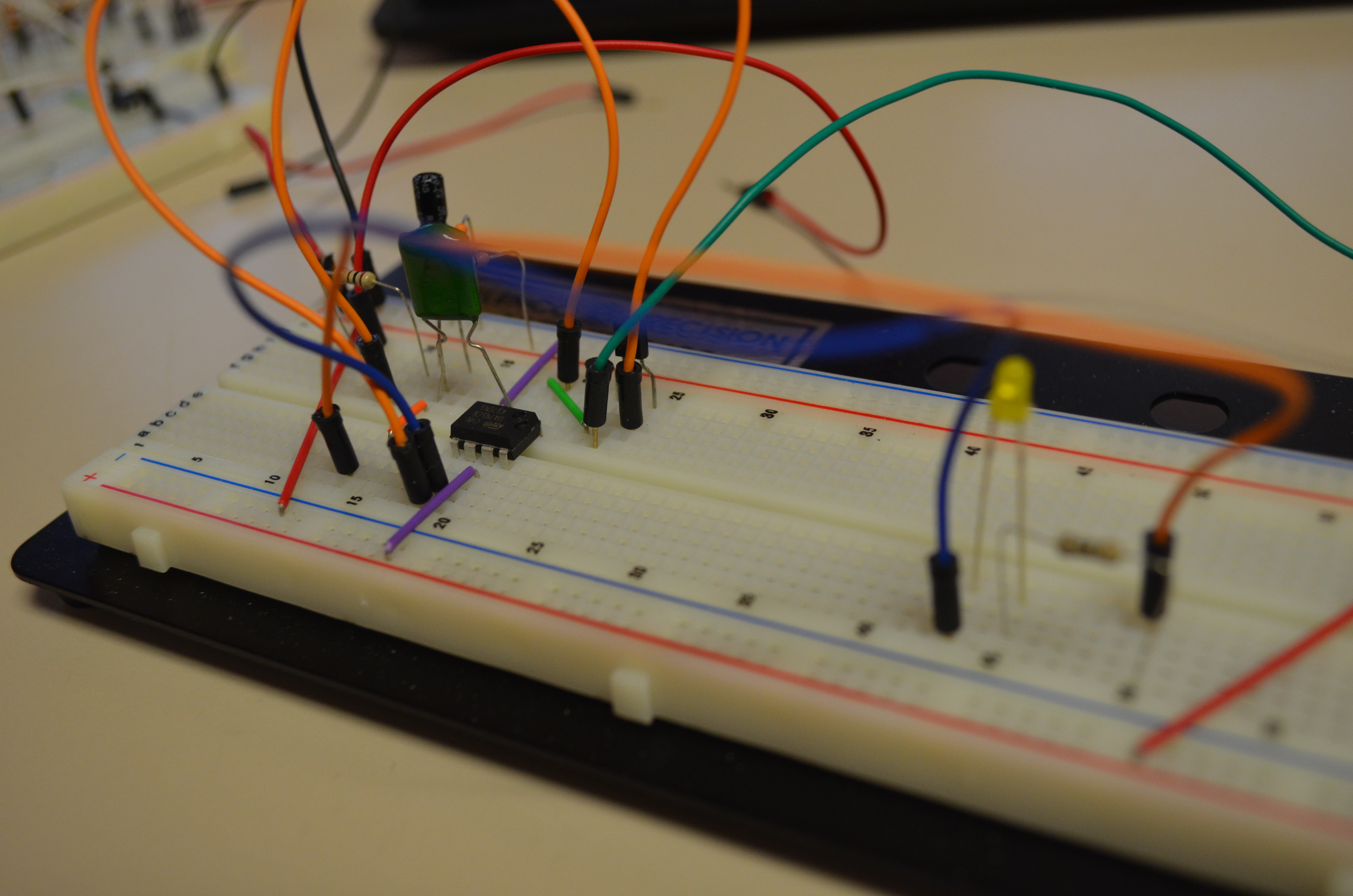
To my great surprise, it didn’t work perfectly on the first try. I tried shortening the delay, thinking that it might simply be too long, but that didn’t work either.
I poked around the circuit with a multimeter, trying to figure out which part of the circuit wasn’t pulling its weight. Turns out that it was the sample-and-hold circuit. For some reason, the voltage output was lower than the voltage input.
I didn’t bother trying to figure out what went wrong because at this point, I suddenly began wondering why the heck I was even trying to latch an analog signal at all. Why wouldn’t I just latch a digital value instead? After all, I only need eight bits.
IDEA #2: A GAZILLION FLIP FLOPS
Why I didn’t think to simply convert the analog voltage back into a digital one for easy latching, I don’t know. But whatever. I began conceptualizing another circuit, not so different from the above. All I needed to do was convert the analog signal into an 8-bit digital signal. Then, I could easily latch those eight bits in a set of flip flops, and I wouldn’t have to worry about any of this voltage decay nonsense.
Although theoretically a much more reliable solution, I still would have had a nightmare of a circuit to build — even more nightmarish now that I had eight flip flops per array.
Oh, and I forgot to mention that we were planning on using RGB LEDs, so I’d have to triple my data outputs and digital latches. Yikes.
Luckily, Anisha found something on Sparkfun that pretty much made all my efforts for the past week unnecessary.
IDEA #3: RGB LED String
Thank goodness Anisha found this. It was fun to think about these weird solutions, but honestly I don’t know how I could have possibly managed either of the above two ideas.
Anyway these RGB LED strings work using a serial two-wire interface. Each LED on the string has its own LED driver, which takes in serial data and repeats it to the next driver in the chain. It’s not exactly like the master-slave design in the commonly-used I2C; rather than each “slave” device being connected to a single, common open-drain line, the “slaves” in this design each have their own serial inputs and outputs. I haven’t looked deeply into how it works, but the way it’s set up seems to suggest that unique addressing is not necessary. Because the signal has to be routed through each node, it’s easy to simply keep track of how many nodes the signal has passed through and use that information as an address instead. I’m fairly certain that an unlimited number of these can be chained together (assuming that they’re powered independently). Nifty!